Search This Blog

Sunday, March 22, 2015

Linux Host Virtualization Networking


Optimizing and testing Linux Layer 2 and Layer 3 host networking tun/tap, bridge and routing options for host-to-VM and VM-to-VM connectivity for QEMU/KVM, VirtualBox and GNS3.  Includes performance tests for QEMU/KVM networking options that indicate 12.0 Gb/s to 18.8 Gb/sec sustained throughput for Linux host switching and routing.

Introduction

Linux distributions -- through the kernel and additional packages -- includes support for a variety of Layer 2 and Layer 3 networking features.  At Layer 2, it supports bridges, switching and VLANs.  At Layer 3, it supports IP routing and routing protocols such as RIP, OSPF, EIGRP, etc.  This article illustrates configuring various Linux host networking features to provide connectivity between GNS3 and QEMU/KVM networks.

The current Linux networking toolkit is iproute2 -- replacing older net-tools (ifconfig, ARP, etc.) and other (bridge-utils, tunctl, vlan, etc.) with one package.  However, some of the features in the older tools are still useful and will be installed.

The host laptop has quad-core Core i5 3230M, 2.60 GHz processors and 6 GB memory.  The QEMU/KVM VMs used for testing were assigned 4 cores each and 2 GB memory.

Linux Layer 2 Features

Layer 2 of the OSI model -- the Data Link Layer -- provides a variety of lower-level services.  Frames use Media Access Control (MAC) addresses to identify the source and destination addresses on a single Local Area Network.  MAC addresses are hard-coded into network interfaces (although they may be changed is the operating system supports that) and unique.  Destination addresses are discovered with broadcasts (and ARP) that flood the LAN; a single LAN is a broadcast domain.  Switching and bridging refers to transmitting frames from source to destination based upon MAC addresses.  Traditionally, a bridge has two interfaces and a switch more than two.  Thus, Layer two only operates on LANs and requires higher-level networking to transmit between LANs.

Linux Layer 2 Switching and Bridging

The current iproute2 toolkit may be used to create bridged interfaces.  However, there is additional functionality on the older bridge-utils toolkit that also integrates more easily with the Debian-style /etc/network/interfaces configuration file.

Linux tun and tap Devices

These are pseudo devices created in software and not physical ones.  At Layer 3, tun devices work at the packet level and typically used for tunnelling protocols.  For switching, tap devices operates at the Data Link layer and simulate a single interface.

You may use the older bridge-utils tunctl command or newer iproute2 command to create tap devices:
tunctl -t tap0
or
ip tuntap add tap0 mode tap
You may also create these devices at boot time using the Debian-style /etc/network/interfaces file:
auto tap0
iface tap0 inet manual
pre-up tunctl -t tap0
or
pre-up ip tuntap add tap0 mode tap
 The devices may also be configured with IP addresses by specifying "iface tap0 inet static" and the address, netmask and (optionally) gateway.

Linux Bridges and Switches

Bridges and switches -- multiport bridges -- are also available.  For the balance of this section, I will refer to both bridges and switches as bridges.  They are quite flexible in that you do not have to define specific ports as members or even a total number of logical ports in a bridge. The newer iproute2 toolkit supports creating bridges, however the older bridge-utils package is (in the author's opinion) easier to use and provides more granular control of bridge configuration.  From the brctl help command:


  • addbr         <bridge>        add bridge
  • delbr         <bridge>        delete bridge
  • addif         <bridge> <device>    add interface to bridge
  • delif         <bridge> <device>    delete interface from bridge
  • hairpin       <bridge> <port> {on|off}    turn hairpin on/off
  • setageing     <bridge> <time>        set ageing time
  • setbridgeprio    <bridge> <prio>        set bridge priority
  • setfd         <bridge> <time>        set bridge forward delay
  • sethello      <bridge> <time>        set hello time
  • setmaxage     <bridge> <time>        set max message age
  • setpathcost    <bridge> <port> <cost>    set path cost
  • setportprio    <bridge> <port> <prio>    set port priority
  • show          [ <bridge> ]        show a list of bridges
  • showmacs      <bridge>        show a list of mac addrs
  • showstp       <bridge>        show bridge stp info
  • stp           <bridge> {on|off}    turn stp on/off
For this article, we will focus on creating bridges at boot time in the /etc/network/interfaces file:
auto br0
iface br0 inet static
address 172.31.254.1
netmask 255.255.255.0
bridge_stp on
bridge_fd 0
bridge_ports tap0
These specify a bridge with an address and netmask (but no gateway) with a single defined interface -- tap0.  Spanning Tree Protocol -- to identify and prevent bridge loops -- is enabled and there is no forwarding delay when the bridge becomes active.  More interfaces may be added to the bridge using virtual networking -- such as GNS3 and QEMU/KVM, but more on that later.

It is not necessary to use tap interfaces with numbered, empty bridges.  Some virtualization technologies, such as VirtualBox, refer to this as Host-Only Networking because the VMs can communicate with each other and the host, but not outside networks.  Simply omit the bridge_ports definition:
auto br0
iface br0 inet static
address 172.31.254.1
netmask 255.255.255.0
bridge_stp on
bridge_fd 0
In the above case, tap0 is the operating system's logical interface connection to the bridge. It does not have to be numbered as the OS will recognize the bridge itself as having the assigned IP address. You are not limited to adding host tap interfaces to the bridge and physical Ethernet devices may be added as well. Wireless interfaces may also be added, but require additional configuration that will not be addressed in this article.

Layer 2 Host Networking Performance

bandwidth is an important consideration and there is a lot of misinformation about Linux tun and tap performance scattered around the Internet -- further proving the satirical adage "I read it on the Internet, it must be true!"  The author's limited searches suggested tap interfaces "theoretically" perform at up to 160 Mb/s, but in reality perform at under 10 Mb/s (less than a 20-year-old Ethernet NIC).

The following output is from a 60-second iperf test between the host (Ubuntu 14.04 Desktop) and a QEMU/KVM virtual machine (Debian Wheezy) over a tap/bridge connection:
~$ iperf -c 172.31.253.2 -t 60 -i 10
------------------------------------------------------------
Client connecting to 172.31.253.2, TCP port 5001
TCP window size:  136 KByte (default)
------------------------------------------------------------
[  3] local 172.31.253.1 port 50211 connected with 172.31.253.2 port 5001
[ ID] Interval       Transfer     Bandwidth
[  3]  0.0-10.0 sec  21.7 GBytes  18.7 Gbits/sec
[  3] 10.0-20.0 sec  22.5 GBytes  19.3 Gbits/sec
[  3] 20.0-30.0 sec  21.8 GBytes  18.7 Gbits/sec
[  3] 30.0-40.0 sec  21.3 GBytes  18.3 Gbits/sec
[  3] 40.0-50.0 sec  21.9 GBytes  18.8 Gbits/sec
[  3]  0.0-60.0 sec   131 GBytes  18.8 Gbits/sec
The following output is from a 60-second iperf test between the host (Ubuntu 14.04 Desktop) and a QEMU/KVM virtual machine (Debian Wheezy) over a bridge (no tap interface) connection:
~$ iperf -c 172.31.254.3 -t 60 -i 10
------------------------------------------------------------
Client connecting to 172.31.254.3, TCP port 5001
TCP window size: 85.0 KByte (default)
------------------------------------------------------------
[  3] local 172.31.254.1 port 34266 connected with 172.31.254.3 port 5001
[ ID] Interval       Transfer     Bandwidth
[  3]  0.0-10.0 sec  21.6 GBytes  18.5 Gbits/sec
[  3] 10.0-20.0 sec  20.9 GBytes  18.0 Gbits/sec
[  3] 20.0-30.0 sec  21.0 GBytes  18.1 Gbits/sec
[  3] 30.0-40.0 sec  21.6 GBytes  18.6 Gbits/sec
[  3] 40.0-50.0 sec  21.1 GBytes  18.2 Gbits/sec
[  3] 50.0-60.0 sec  22.0 GBytes  18.9 Gbits/sec
[  3]  0.0-60.0 sec   128 GBytes  18.4 Gbits/sec

The following output is from a 60-second iperf test between the two QEMU/KVM virtual machines (Debian Wheezy) over a tap/bridge connection:
~# iperf -c 172.31.253.2 -t 60 -i 10
------------------------------------------------------------
Client connecting to 172.31.253.2, TCP port 5001
TCP window size: 23.5 KByte (default)
------------------------------------------------------------
[  3] local 172.31.253.3 port 33823 connected with 172.31.253.2 port 5001
[ ID] Interval       Transfer     Bandwidth
[  3]  0.0-10.0 sec  14.1 GBytes  12.1 Gbits/sec
[  3] 10.0-20.0 sec  14.3 GBytes  12.3 Gbits/sec
[  3] 20.0-30.0 sec  14.5 GBytes  12.4 Gbits/sec
[  3] 30.0-40.0 sec  14.3 GBytes  12.3 Gbits/sec
[  3] 40.0-50.0 sec  14.2 GBytes  12.2 Gbits/sec
[  3]  0.0-60.0 sec  84.1 GBytes  12.0 Gbits/sec

The following output is from a 60-second iperf test between the two QEMU/KVM virtual machines (Debian Wheezy) over a bridge (no tap interface) connection:
~# iperf -c 172.31.254.2 -t 60 -i 10
------------------------------------------------------------
Client connecting to 172.31.254.2, TCP port 5001
TCP window size: 23.5 KByte (default)
------------------------------------------------------------
[  3] local 172.31.254.3 port 59334 connected with 172.31.254.2 port 5001
[ ID] Interval       Transfer     Bandwidth
[  3]  0.0-10.0 sec  16.0 GBytes  13.7 Gbits/sec
[  3] 10.0-20.0 sec  16.1 GBytes  13.8 Gbits/sec
[  3] 20.0-30.0 sec  16.1 GBytes  13.8 Gbits/sec
[  3] 30.0-40.0 sec  15.8 GBytes  13.5 Gbits/sec
[  3] 40.0-50.0 sec  15.4 GBytes  13.2 Gbits/sec
[  3]  0.0-60.0 sec  95.0 GBytes  13.6 Gbits/sec

Properly configured, Layer 2 networking performance between Linux hosts and VMs is excellent.  Bandwidth between VMs is less than between host and VM; a 13.3% performance improvement was realized by using bridges without a host tap interface.

Adding Virtual Machine Interfaces to Linux Layer 2 Devices

QEMU/KVM


Using the Qemu/KVM Virtual Machine Manager is the easiest way to connect to host machine networks.  Virtual Machine Manager automatically recognizes configured host tap/bridge devices and offers to bridge its own virtual NICs to a tap interface.
The choice of NIC models is also important and the paravirtualized Virtio device offers better performance than fully virtualized devices such as Intel e1000 NICs.
 The optimal QEMU/KVM configuration -- an empty bridge (i.e. a host bridge qithout an attached tap interface) is illustrated above.

VirtualBox


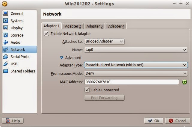
The selections for VirtualBox guests are much the same as for QEMU/KVM guests.  Under Network, select "Bridged Adapter" and "tap0" (or another tap interface if so desired).  Open the Advanced settings and select the Paravirtualized Network (virtio-net).

GNS3

GNS3 connections to the host are more detailed and have been described in another post.

Linux Layer 3 Routing

The Linux kernel supports static Layer 3 IP routing.  However, virtualized environments (particularly using GNS3) are better served by routing protocols.  This article describes how to implement a relatively portable OSPF configuration that, with minimal configuration, connects virtual machines and networks to the Internet.

Quagga Routing Protocols

Quagga is a fork of the inactive Zebra project.  For the subject host, it will implement OSPF to route between the host, Internet and virtual networks.  A previous post discusses the topic in detail.

For this implementation, the backbone area (range 172.16.0.0/12) will be the host Linux laptop itself.  The wireless network's DHCP network and tap/bridge interfaces will be areas attached to the backbone.

Layer 3 VM Networking Performance

Layer 3 routing between networks typically involves additional overhead and resulting lower speeds than Layer 2 switching.  Under Linux host networking using two different numbered bridges (without tap interfaces), there appears to be a small degree of such reduced performance, albeit quite small.
~# iperf -c 172.31.254.2 -t 60 -i 10
------------------------------------------------------------
Client connecting to 172.31.254.2, TCP port 5001
TCP window size: 23.5 KByte (default)
------------------------------------------------------------
[  3] local 172.31.253.3 port 57056 connected with 172.31.254.2 port 5001
[ ID] Interval       Transfer     Bandwidth
[  3]  0.0-10.0 sec  15.3 GBytes  13.2 Gbits/sec
[  3] 10.0-20.0 sec  15.2 GBytes  13.1 Gbits/sec
[  3] 20.0-30.0 sec  15.4 GBytes  13.2 Gbits/sec
[  3] 30.0-40.0 sec  15.3 GBytes  13.1 Gbits/sec
[  3] 40.0-50.0 sec  14.6 GBytes  12.6 Gbits/sec
[  3] 50.0-60.0 sec  14.4 GBytes  12.4 Gbits/sec
[  3]  0.0-60.0 sec  90.2 GBytes  12.9 Gbits/sec
 

Host Wireless Adapter

The author uses many wireless networks and they are (fortunately) all configured to assign DHCP addresses in the 192.168.x.x range, although on a variety of different 24-bit CIDR masks.  They also assign a static default gateway.  While it is possible to add a wireless adapter to a bridge, it is easier to configure OSPF to treat the wireless adapter as a non-backbone area.  The following Quagga commands (note the slightly different from Cisco syntax) cover the range of 162.168.x.x addresses to operate correctly under OSPF:
network 192.168.0.0/24 area 192.168.0.0
network 192.168.1.0/24 area 192.168.0.0

...
area 192.168.0.0 range 192.168.0.0/16
default-information originate always 
Please note that a separate network definition must be applied for each different subnet the wireless LAN interface encounters.  This requires adding only one command to the Quagga ospfd.conf file each time a new network is encountered.

Since wireless routers assign a static route to the Linux laptop host, it acts as the default gateway originator (OSPF command "default gateway originate always").  This configuration passes the static default gateway from the backbone to connected OSPF areas -- the virtual networks.

Host tap/bridge Interfaces

The numbered host tap/bridge interfaces may be added to the Quagga routing protocols.  For OSPF, assure they are numbered in the Area 0.0.0.0 Backbone range and add their networks accordingly.  These interfaces will then update the host routing tables and any other connected areas.

Guest Interfaces

Three scenarios are depicted in the illustration above:
  1. VMs individually connected to a bridge
  2. QEMU/KVM or VirtualBox Linux router gateway
  3. GNS3 Cisco router gateway

VMs individually connected to a bridge

This is a basic scenario.  The hosts simply need to connect to the tap or bridge interface, have an address in the same subnet and the gateway defined as the host tap or bridge IP address.

QEMU/KVM or VirtualBox Linux router gateway

A VM acting as a gateway to other VMs behind it requires a routing protocol.  One interface must be connected to the host tap or bridge interface and any others connected to one or more bridges for the other hosts.  These additional bridges may be host bridges (as described in this article) or ones defined in the Virtual Networking software used (e.g. QEMU/KVM, VirtualBox, etc.).  Performance of the additional bridges will be the topic of another post.

GNS3 Cisco router gateway

GNS3 on an Ubuntu host is a bit more complicated affair.  Connecting to host networking requires root access (as depicted in the illustrations below), and this has been problematical for the author.

The interfaces are recognized and GNS3 hosts may connect to other VM hosts on the bridge, but not to the host itself.  As described in another article, under Ubuntu the author uses Cloud devices to connect to the host.
GNS3 also is a software emulator and when emulating Cisco IOS hardware-based routers, performance suffers.  Although this test was conducted using an older version of GNS3 (0.86), the author's anecdotal observations of performance of the current (at the time of writing, 1.2.3) indicates low bandwidth routing performance.

Friday, March 20, 2015

Multi Site Open Monitoring Distribution Configuration

Configuring distributed monitoring using the Open Monitoring Distribution's Nagios - Check_MK - Livestatus - Multisite features.


Introduction

The Open Monitoring Distribution (OMD) provides an easy to install and configure Nagios system with Check_MK.  Check_MK uses the Livestatus broker module to efficiently process host and service checks.  Installation is described in this article.

Installing and configuring distributed Nagios Core monitoring -- using the Nagios Service Check Acceptor (NSCA) or mod_gearman is complicated and time-consuming.  OMD, however, includes menu-driven and web-interface configuration of Check_MK's Multisite feature -- distributed monitoring and centralized configuration.  This article explains how to configure Multisite distributed monitoring.

Configuring the Master Server

The Master Server is the one upon which all configurations are performed.  The Slave servers allow configuration, but the changes will be overwritten when the Master Server updates.

The Master Server must be configured as a local connection.  It requires a URL prefix of the host name, localhost or a valid IP address.  In this example, IP addresses are used and 127.0.0.1 selected as the URL prefix http://127.0.0.1/COU -- the site name is the directory.

Configuring Slave Servers

Enabling Livestatus

Slave servers require some additional work.  First, you must enable Livestatus from the server's menu configuration utility.  Stop the site with the command: "omd stop <site_name>."  The, start the configuration utility with the command "omd config <site_name."  Select "Distributed Monitoring."  Then, enable Livestatus as depicted below.


This creates and configures the file /opt/omd/sites/<site_name>/etc/xinetd.d/check_mk.  This xinetd service listens on TCP port 6557 and the file defines all parameters necessary for Master Server connections.

Creating Master to Slave Replication

Several items must be defined to enable replication:

  1. The Livestatus IP address and TCP port 6557
  2. The URL prefix http://<host_name or IP_address>/<site_name>
  3. Slave replication
  4. The Multisite URL http://<host_name or IP_address>/<site_name>/check_mk

Once configured and live, login to each Slave Server from the Master to enable replication.

Creating Hosts

Creating hosts is almost identical to creating them on single-server installations.  There is an additional -- and important -- field: the "Monitored on site" definition.  This provides a drop-down list of all configured Master and Slave Servers.
Organization is also important.  The author uses folders for each Master and Slave Server, each predefining the corresponding "Monitored on site" value.
The video below depicts the process of configuring OMD Distributed Monitoring.


Wednesday, March 18, 2015

Integrating Open Monitoring Distribution (Nagios-Check-MK) with GNS3

This article demonstrates how to configure a Debian VirtualBox Open Monitoring Distribution using Nagios and Check-MK into an existing GNS3 network of Cisco Routers and Linux Layer 2 Switches.

Introduction

Nagios -- and its fork Icinga -- is one of the most common systems monitoring tools available.  Among its strengths are notifications and topological relationships.  Properly configured, it does not send out large numbers of (meaningless) notifications for an entire subnetwork because the router/switch between it and the monitoring host fails.

There is a great deal to learn about Nagios Core (that ships with many Linux distributions.  A few of the author's own articles provide additional details on how to configure it.

Nagios Basics for Infrastructure

The single most important concept to understand for monitoring switches and routers with Nagios is the Parent relationship.  Nagios provides a field in the host definition that specifies a host between the monitoring server and host.  In the image above, the Monitoring Server is a parent to the COU_Switch.  The COU_Switch -- in turn -- is a parent to both the COU_7206 and COU_3745 Routers.  This is a simple topology and redundant links are a more complicated issue beyond the scope of this article.  Properly defined, when a parent host fails, the child hosts register as Unreachable rather than Down.  When registered as Unreachable, Nagios does not send out alerts.  Thus, if a router fails, it registers as Down and an alert is sent; the child hosts register as Unreachable and no notifications are sent.  This provides a mch simplified set of data to determine the root causes of problems.

The second important concept to understand about Nagios for monitoring switches and routers is the Simple Network Management Protocol (SNMP).  SNMP is an IETF standard for collecting and reporting host information.  Networking equipment generally supports SNMP Version 2c or higher.  In its simplest configuration, SNMP is configured to listen on one or more interfaces and requires a community string (the general default is "public") and will report information to a monitoring host.  See the link at the beginning of this paragraph for more information.


Nagios with Check-MK

Check-MK is an addition to Nagios Core.  Perhaps that is an understatement.  Check-MK provides host agents that automatically poll and return information to the monitoring server.  Livestatus is a broker module that interprets returned host agent data and translates it into Nagios for processing.  Multisite and WATO are web-based configuration and reporting tools.

In short, Check-MK is a tool that greatly simplifies host check configurations.


Installing Nagios with Check-MK on Debian

You may install Check-MK from Debian repository packages.  However, a much simpler method is to download the Open Monitoring Distribution (OMD).  This is a package built for a variety of major distributions.  The following steps are for Debian Wheezy using the current package at the time of writing:
  • Download the 102 Megabyte OMD package:  wget http://files.omdistro.org/releases/debian_ubuntu/omd-1.20.wheezy.amd64.deb
  • Run the command dpkg -i omd* -- this will fail because dependencies are not met but Debian will correct that issue.
  • Run the command: apt-get -f install to add the missing dependencies; you will need to configure MySQL with a root user password.
  • Run the command dpkg -i omd*
Once this is complete, OMD -- with Nagios, Check-MK and a variety of other utilities is installed.   OMD installs into the /opt/omd directory.  Under that are apache, sites and versions.  The primary work area is /opt/omd/sites, where the files configuring each monitoring site are maintained.

The agent package is also available and this may be installed from the Debian repositories using apt.  The agent runs under xinetd, and the configuration file is /etc/xinetd/check_mk.  The last line must be changed from "disable = yes" to "disable = no" at a minimum.  You may also restrict access to specified IP addresses.  Once changed, simply restart xinetd.

Creating a monitoring site is easy.  Issue the command "omd create <site_name>."  For this article, we shall use the site name COU.  This command:
  • creates a directory structure /opt/omd/COU under which configuration files are maintained.
  • a new user and group COU; the user is also a member of the group omd.

You may modify configuration files (e.g. /etc/apache/*, /etc/nagios/*) as necessary, but the distribution is ready to run and configure from the web interface.  Start the site with the command "omd start <site_name>."

Configuring OMD using the Check-MK Web Administration Tool (WATO)

The new site is available under the web server's /COU directory.  The default logon is user name "omdadmin" and password "omd."

The initial page is an overview of different web-based tools such as Nagios, Icinga, Thruk and NagVis.


Check-MK is another web interface that may be used with Nagios, but in this case it is also integrated with the Check-MK suite and includes tools such as WATO for configuration, the Livestatus Nagios event broker and a very efficient Check Engine that submits results to Nagios as passive checks, saving a great deal of processing -- an effective alternative to NSCA.

WATO, the administration tool, provides a well-organized interface.  The illustration above depicts the Hosts option, with the monitoring server and two Folders for Cisco and Linux devices added.  The add hosts and folders icons link to the screens for these tasks.
The Cisco Folder contains eight routers with icons and summaries provided for administrative tasks such as modifying and cloning hosts.
The edit and add hosts screens are very similar.  Check-MK is agent or SNMP-based, so there is very little information required to define a host -- the application, agents and SNMP manage discovery.
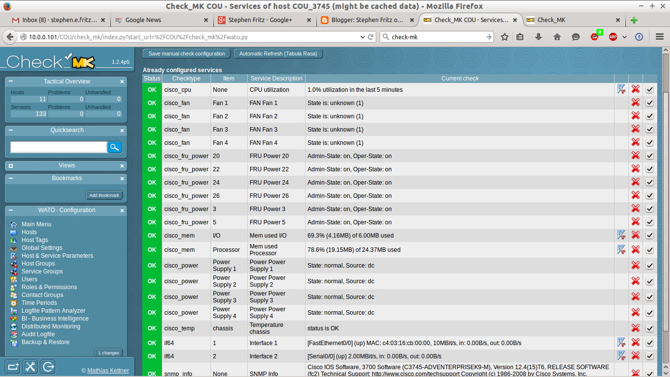
The discovery process is fairly thorough.  The illustration above depicts SNMP items discovered on a Cisco 3745 Router.  Discovery finds not just interfaces, but also fans, power supplies, CPU, memory and other counters.

By default, the SNMP Discovery process only searches for Ethernet and Frame Relay devices on all hosts.  If you have SONET or other interfaces, you must activate them from the Global Configuration screen.  That process is depicted in the video at the bottom of this article.
Parent relationship definitions are included for each host.  Parent relationships define topology -- as depicted above -- and also control Notifications.  A more thorough treatment discussion of Nagios/Icinga Logic, Alerts and Notifications is available in another blog article.  The illustration above depicts a NagVis-generated topology available from the Check-MK views.
Finally (at least as far as this article is concerned), OMD includes a preconfigured PNP4Nagios installation.  As soon as a host is added the application processes service check results and begins graphing them.  Although not depicted, Check-MK includes its own Perf-O-Meter views that are small and effective overviews of counters.
The video below depicts OMD installation on Debian Wheezy, a rather simple process described above.


The video below depicts configuring OMD for monitoring eight Cisco routers and two Linux Layer 2 Switches using the Check-MK interface.

Tuesday, February 17, 2015

GNS3 - VirtualBox Part 11: Debian/Ubuntu Bonded NIC Layer 2 Switches

This article demonstrates how to configure Debian/Ubuntu VirtualBox guests to operate as Layer 2 switches with bonded NICs, aggregating several adapters into higher-speed logical interfaces.


Introduction

There have been many implementations of adapter bonding -- often vendor-specific and proprietary; these implementations are not germane to this article.  Over time, published standards have replaced proprietary ones.  Linux supports seven different bonding types and a Linux Bonding HOW-TO document is available at kernel.org.

This article describes Mode 4, IEEE 802.3ad Dynamic link aggregation.  This is a common implementation and requires switch support.  It is widely supported by vendors.

Bonding Modes

Specifies one of the bonding policies. The default is balance-rr (round robin). Possible values are: 

Balance-rr or 0

Round-robin policy: Transmit packets in sequential order from the first available slave through the last. This mode provides load balancing and fault tolerance.

Active-Backup or 1

Active-backup policy: Only one slave in the bond is active. A different slave becomes active if, and only if, the active slave fails. The bond's MAC address is externally visible on only one port (network adapter) to avoid confusing the switch. This mode provides fault tolerance.

Balance-XOR or 2

XOR policy: Transmit based on the selected transmit hash policy. The default policy is a simple [(source MAC address XOR'd with destination MAC address XOR packet type ID) modulo slave count]. Alternate transmit policies may be selected via the xmit_hash_policy option. This mode provides load balancing and fault tolerance. 

Broadcast or 3

Broadcast policy: transmits everything on all slave interfaces. This mode provides fault tolerance.

802.3ad or 4

IEEE 802.3ad Dynamic link aggregation. Creates aggregation groups that share the same speed and duplex settings. Utilizes all slaves in the active aggregator according to the 802.3ad specification. Slave selection for outgoing traffic is done according to the transmit hash policy, which may be changed from the default simple XOR policy via the xmit_hash_policy option. Most switches will require some type of configuration to enable 802.3ad mode. This mode provides load balancing and fault tolerance.

Balance-TLB or 5

Adaptive transmit load balancing: channel bonding that does not require any special switch support. In tlb_dynamic_lb=1 mode; the outgoing traffic is distributed according to the current load (computed relative to the speed) on each slave. In tlb_dynamic_lb=0 mode; the load balancing based on current load is disabled and the load is distributed only using the hash distribution. Incoming traffic is received by the current slave. If the receiving slave fails, another slave takes over the MAC address of the failed receiving slave.

Balance-ALB or 6

Adaptive load balancing: includes balance-tlb plus receive load balancing (rlb) for IPV4 traffic, and does not require any special switch support. The receive load is distributed sequentially (round robin) among the group of highest speed slaves in the bond. When a link is reconnected or a new slave joins the bond the receive traffic is redistributed among all active slaves in the bond.


Installing ifenslave and Modifying Configuration Files

The first step is to install the ifenslave package (apt-get install ifenslave).  The package includes the commands and kernel module support.  Boot time kernel module loading requires adding a line -- bonding -- to /etc/modules thus:
# /etc/modules: kernel modules to load at boot time.
#
# This file contains the names of kernel modules that should be loaded
# at boot time, one per line. Lines beginning with "#" are ignored.
# Parameters can be specified after the module name.

lp
rtc
bonding


A new file -- etc/modprobe.d/modules.conf -- is required for additional configuration.  While many configuration commands may be later added to the /etc/network/interfaces file, they may also be added to this one.

alias bond0 bonding
options bonding mode=4 miimon=100 downdelay=200 updelay=200 max_bonds=2
alias bond1 bonding
options bonding mode=4 miimon=100 downdelay=200 updelay=200 max_bonds=2

The illustrated options are not mandatory, but advisable.  The miimon option specifies the interval (milliseconds) in which MII Link Monitoring occurs.  The default value is 0 and disables MII Link Monitoring.  The downdelay and updelay options specify delay times (milliseconds) between MII Link Monitoring detection of a state change and application of the change; it is a multiple of the miimon value and will be automatically rounded if otherwise defined.  Another important option is "maxbonds=#."  The default for this value is 1 and it allows (but does not automatically create) a bond0 interface.  If you plan to add more than one bonded interface, you will need to specify "maxbond=#" as a larger value.
Additional configuration options are detailed in the kernel.org Linux Bonding HOW-TO document.

Configuring from the Command Line Interface

Bonded interfaces may be configured from the command line or added to the /etc/rc.local file.  The following commands utilize iproute2, ifenslave and the deprecated bridge-utils packages:
ifenslave bond0 eth0 eth1
ifenslave bond1 eth2 eth3 eth4

ip link set bond0 up
ip link set bond1 up
ip link add dev br0 type bridge
ip link set dev bond0 master br0
ip link set dev bond1 master br0
ip addr add 10.64.0.4/255.255.255.0 dev br0ip route add default via 10.64.0.1ip link set dev br0 upbrctl stp br0 on
It is not necessary to set the individual Ethernet adapters to "up" when using bonded interfaces.  However, if unbonded Ethernet adapters are to be used in the bridge, they must be set to "up" thus:
ip link set dev eth5 up

Configuring /etc/network/interfaces

Alternatively, bonded Ethernet interfaces may also be configured in the /etc/network/interfaces file, providing support for the ifupdown package for high-level configuration.   The following configuration creates a bridge (br0) with a static IP address, two bonds (bond0 = eth0 and eth1; bond1 = eth2, eth3 and eth4) and three Ethernet interfaces (eth5, eth6 and eth7) that are members of bridge br0.

auto lo
iface lo inet loopback

auto bond0
iface bond0 inet manual
pre-up ifenslave bond0 eth0 eth1
post-up ip link set dev bond0 master br0
pre-down ip link set dev bond0 nomaster
post-down ifenslave -d bond0 eth0 eth1

auto bond1
iface bond1 inet manual
pre-up ifenslave bond1 eth2 eth3 eth4
post-up ip link set dev bond1 master br0
pre-down ip link set dev bond1 nomaster
post-down ifenslave -d bond1 eth2 eth3 eth4
 

iface eth5 inet manual


iface eth6 inet manual

iface eth6 inet manual


auto br0
iface br0 inet static
address 10.64.0.4
netmask 255.255.255.0
gateway 10.64.0.1
dns_nameservers 192.168.1.1 8.8.8.8 4.4.4.4

bridge_stp on
bridge_waitport 0
bridge_fd 0
bridge_ports bond0 bond1 eth5 eth6 eth7

Testing the Switches

The Legacy ifconfig Command

This command is of limited utility for bonded interfaces.  Note that it lists the bond and Ethernet interfaces as up and whether they are masters (bonds) or slaves (Ethernet).  It does not specify details of master-slave relationships.
bond0     Link encap:Ethernet  HWaddr 08:00:27:1c:e8:ec 
          inet6 addr: fe80::a00:27ff:fe1c:e8ec/64 Scope:Link
          UP BROADCAST RUNNING MASTER MULTICAST  MTU:1500  Metric:1
          RX packets:420 errors:0 dropped:3 overruns:0 frame:0
          TX packets:576 errors:0 dropped:0 overruns:0 carrier:0
          collisions:0 txqueuelen:0
          RX bytes:46060 (46.0 KB)  TX bytes:52141 (52.1 KB)

bond1     Link encap:Ethernet  HWaddr 08:00:27:83:45:d7 
          UP BROADCAST RUNNING MASTER MULTICAST  MTU:1500  Metric:1
          RX packets:72 errors:0 dropped:2 overruns:0 frame:0
          TX packets:473 errors:0 dropped:0 overruns:0 carrier:0
          collisions:0 txqueuelen:0
          RX bytes:8736 (8.7 KB)  TX bytes:38259 (38.2 KB)

br0       Link encap:Ethernet  HWaddr 08:00:27:1c:e8:ec 
          inet addr:10.64.0.4  Bcast:10.64.0.255  Mask:255.255.255.0
          inet6 addr: fe80::a00:27ff:fe1c:e8ec/64 Scope:Link
          UP BROADCAST RUNNING MULTICAST  MTU:1500  Metric:1
          RX packets:367 errors:0 dropped:1 overruns:0 frame:0
          TX packets:212 errors:0 dropped:0 overruns:0 carrier:0
          collisions:0 txqueuelen:0
          RX bytes:34606 (34.6 KB)  TX bytes:27137 (27.1 KB)

eth0      Link encap:Ethernet  HWaddr 08:00:27:1c:e8:ec 
          UP BROADCAST RUNNING SLAVE MULTICAST  MTU:1500  Metric:1
          RX packets:88 errors:0 dropped:0 overruns:0 frame:0
          TX packets:32 errors:0 dropped:0 overruns:0 carrier:0
          collisions:0 txqueuelen:1000
          RX bytes:8736 (8.7 KB)  TX bytes:3604 (3.6 KB)

...

eth4      Link encap:Ethernet  HWaddr 08:00:27:83:45:d7 
          UP BROADCAST RUNNING SLAVE MULTICAST  MTU:1500  Metric:1
          RX packets:26 errors:0 dropped:2 overruns:0 frame:0
          TX packets:38 errors:0 dropped:0 overruns:0 carrier:0
          collisions:0 txqueuelen:1000
          RX bytes:3032 (3.0 KB)  TX bytes:6982 (6.9 KB)

The ip addr Command

This command -- part of the newer iproute2 package -- provides detailed information about interfaces states and master-slave relationships.  For instance, Ethernet interfaces eth0, eth1 and eth2 enumerate bond0 as their masters and bond0 is enumerates br0 as its master.
2: eth0: <BROADCAST,MULTICAST,SLAVE,UP,LOWER_UP> mtu 1500 qdisc pfifo_fast master bond0 state UP group default qlen 1000
    link/ether 08:00:27:1c:e8:ec brd ff:ff:ff:ff:ff:ff
3: eth1: <BROADCAST,MULTICAST,SLAVE,UP,LOWER_UP> mtu 1500 qdisc pfifo_fast master bond0 state UP group default qlen 1000
    link/ether 08:00:27:1c:e8:ec brd ff:ff:ff:ff:ff:ff
...
9: eth7: <BROADCAST,MULTICAST> mtu 1500 qdisc noop state DOWN group default qlen 1000
    link/ether 08:00:27:81:dd:5a brd ff:ff:ff:ff:ff:ff
10: bond0: <BROADCAST,MULTICAST,MASTER,UP,LOWER_UP> mtu 1500 qdisc noqueue master br0 state UP group default
    link/ether 08:00:27:1c:e8:ec brd ff:ff:ff:ff:ff:ff
    inet6 fe80::a00:27ff:fe1c:e8ec/64 scope link
       valid_lft forever preferred_lft forever
11: bond1: <BROADCAST,MULTICAST,MASTER,UP,LOWER_UP> mtu 1500 qdisc noqueue master br0 state UP group default
    link/ether 08:00:27:83:45:d7 brd ff:ff:ff:ff:ff:ff
12: br0: <BROADCAST,MULTICAST,UP,LOWER_UP> mtu 1500 qdisc noqueue state UP group default
    link/ether 08:00:27:1c:e8:ec brd ff:ff:ff:ff:ff:ff
    inet 10.64.0.4/24 brd 10.64.0.255 scope global br0
       valid_lft forever preferred_lft forever
    inet6 fe80::a00:27ff:fe1c:e8ec/64 scope link
       valid_lft forever preferred_lft forever

Listing /proc/net/bonding Files

The /proc/net/bonding file contains bond-specific information, this time for a different switch using bonded Ethernet adapters eth2, eth3 and eth4.  Notice that the bond Transmit Hash Policy is the default Layer 2.  Also notice that the default LACP rate -- slow -- applies.  LACP is the protocol that negotiates bundling between complaint switches.  The default interval is slow (30 seconds) while fast (1 second) must be manually-specified.
Bonding Mode: IEEE 802.3ad Dynamic link aggregation
Transmit Hash Policy: layer2 (0)
MII Status: up
MII Polling Interval (ms): 100
Up Delay (ms): 200
Down Delay (ms): 200

802.3ad info
LACP rate: slow
Min links: 0
Aggregator selection policy (ad_select): stable
Active Aggregator Info:
    Aggregator ID: 1
    Number of ports: 3
    Actor Key: 17
    Partner Key: 17
    Partner Mac Address: 08:00:27:74:2e:0d

Slave Interface: eth2
MII Status: up
Speed: 1000 Mbps
Duplex: full
Link Failure Count: 0
Permanent HW addr: 08:00:27:83:45:d7
Aggregator ID: 1
Slave queue ID: 0

Slave Interface: eth3
MII Status: up
Speed: 1000 Mbps
Duplex: full
Link Failure Count: 0
Permanent HW addr: 08:00:27:1d:37:ae
Aggregator ID: 1
Slave queue ID: 0

Slave Interface: eth4
MII Status: up
Speed: 1000 Mbps
Duplex: full
Link Failure Count: 0
Permanent HW addr: 08:00:27:7e:25:d0
Aggregator ID: 1
Slave queue ID: 0

The Legacy brctl Commands

The legacy bridge-utils package provides three commands -- brctl show, brctl showmacs and brctl showstp -- that provide an overview of basic bridge configuration and operation.

brctl show <bridge_name>

brctl show br0
bridge name    bridge id        STP enabled    interfaces
br0        8000.0800271ce8ec    yes              bond0
                                                                 bond1

brctl showmacs <bridge_name>

brctl showmacs br0
port no    mac addr        is local?    ageing timer
  1    08:00:27:1c:e8:ec    yes           0.00
  2    08:00:27:83:45:d7    yes           0.00
  1    ca:02:10:48:00:06    no           0.00

brctl showstp <bridge_name>

brctl showstp br0
br0
 bridge id        8000.0800271ce8ec
 designated root    8000.0800271ce8ec
 root port           0                                 path cost           0
 max age          20.00                           bridge max age          20.00
 hello time           2.00                          bridge hello time       2.00
 forward delay           2.00                     bridge forward delay       2.00
 ageing time         300.00
 hello timer           0.10                         tcn timer           0.00
 topology change timer       0.00            gc timer         141.52
 flags           


bond0 (1)
 port id        8001                                      state             forwarding
 designated root    8000.0800271ce8ec       path cost           4
 designated bridge    8000.0800271ce8ec    message age timer       0.00
 designated port    8001                             forward delay timer       0.00
 designated cost       0                               hold timer           0.00
 flags           

bond1 (2)
 port id        8002                                      state             forwarding
 designated root    8000.0800271ce8ec       path cost         100
 designated bridge    8000.0800271ce8ec    message age timer       0.00
 designated port    8002                             forward delay timer       0.00
 designated cost       0                               hold timer           0.00
 flags           

GNS3 Configuration

The GNS3 configuration depicted at the top of this article depicts three Linux switches -- PHL-Core, PHL-Servers and PHL-Storage.  PHL-Core is connected to two routers over bridged Ethernet ports eth0 and eth1; it is connected to PHL-Servers over the bridged two-adapter bond0 interface (eth2 and eth3 to eth0 and eth1, respectively).  PHL-Servers is connected to bridged three-adapter bond1 interface (eth2, eth3 and eth4 to eth0, eth1 and eth2, respectively).  The /etc/network/interfaces files for the three configurations are below.

PHL-Core Configuration

auto lo
iface lo inet loopback

auto bond0
iface bond0 inet manual
pre-up ifenslave bond0 eth2 eth3
post-up ip link set dev bond0 master br0
pre-down ip link set dev bond0 nomaster
post-down ifenslave -d bond0 eth2 eth3

auto br0
iface br0 inet static
address 10.64.0.2
netmask 255.255.255.0
gateway 10.64.0.1
dns-nameservers 192.168.1.1 8.8.8.8 4.4.4.4
bridge_stp on
bridge_waitport 0
bridge_fd 0
bridge_ports eth0 eth1 bond0

iface eth0 inet manual

iface eth1 inet manual

PHL-Servers Configuration

auto lo
iface lo inet loopback

auto bond0
iface bond0 inet manual
pre-up ifenslave bond0 eth0 eth1
post-up ip link set dev bond0 master br0
pre-down ip link set dev bond0 nomaster
post-down ifenslave -d bond0 eth0 eth1

auto bond1
iface bond1 inet manual
pre-up ifenslave bond1 eth2 eth3 eth4
post-up ip link set dev bond1 master br0
pre-down ip link set dev bond1 nomaster
post-down ifenslave -d bond1 eth2 eth3 eth4

auto br0
iface br0 inet static
address 10.64.0.4
netmask 255.255.255.0
gateway 10.64.0.1
dns-nameservers 192.168.1.1 8.8.8.8 4.4.4.4
bridge_stp on

bridge_waitport 0
bridge_fd 0
bridge_ports bond0 bond1

PHL-Storage Configuration

auto lo
iface lo inet loopback

auto bond0
iface bond0 inet manual
pre-up ifenslave bond0 eth0 eth1 eth2
post-up ip link set dev bond0 master br0
pre-down ip link set dev bond0 nomaster
post-down ifenslave -d bond0 eth0 eth1

auto br0
iface br0 inet static
address 10.64.0.5
netmask 255.255.255.0
gateway 10.64.0.1
dns-nameservers 192.168.1.1 8.8.8.8 4.4.4.4
bridge_stp on

bridge_waitport 0
bridge_fd 0
bridge_ports bond0


Sunday, February 15, 2015

GNS3 - VirtualBox Part 10: Debian/Ubuntu bridge-utils/iproute2 Layer 2 Switches

Debian and Ubuntu Linux provide Layer 2 bridges with the older (and deprecated) bridge-utils package and newer iproute2 package.  This article demonstrates implementing bridges using both.

Introduction

Default Debian/Ubuntu installations include the iproute2 package.  The "ip" family of commands is more stable then the commands it supersedes, such as arp, ifconfig and route.  The iproute2 package also supersedes two older Linux bridge packages: bridge-utils and vlan.  However, the author finds configuring networking in the /etc/network/interfaces file simpler using the bridge-utils package; definitions that require scripting using iproute2 require minimal statements using bridge-utils.  Thus, this article incorporates both iproute2 and bridge-utils commands to configure bridges.

Initial Configuration

The initial VirtualBox installation uses Ubuntu Server 14.04 with eight NICs, only one of which is configured.  The /etc/network/interfaces file consists of:

auto lo
iface lo inet loopback

auto eth0
iface eth0 inet static
address 10.64.0.2
netmask 255.255.255.0
gateway 10.64.0.1
dns-nameservers 192.168.1.1 8.8.8.8 4.4.4.4
This configures interface eth0 with an IP address, gateway and name servers, the first of which is the local wireless LAN router.  A Cisco 7206 router has two Gigabit Ethernet interfaces, one (10.64.0.1) for the Ubuntu switch and the other (172.16.0.2) for a connection to a tun/tap device on the host laptop.  The host laptop and Cisco 7206 routers use OSPF to manage routing from the virtual environment, local wireless LAN (192.168.1.0/24) and default gateway.

Configuring the Layer 2 Switch

As mentioned above, the author adds the bridge-utils package (sudo apt-get install bridge-utils).  The bridge-utils package provides several statements that are used in the /etc/network/interfaces file.  The iproute2 commands create the bridge and bridge-utils commands configure it at boot time.  The following is an annotated /etc/network/interfaces file:
auto lo
iface lo inet static

auto br0
iface br0 inet static
address 10.64.0.2
netmask 255.255.255.0
gateway 10.64.0.1
dns-nameservers 192.168.1.1 8.8.8.8 4.4.4.4
bridge_stp on #bridge-utils commad to enable Spanning Tree Protocol
bridge_waitport 0 #bridge-utils commad to set immediate availability
bridge_fd 0 #bridge-utils commad to set no forwarding delay
bridge_ports eth0 eth1 eth2 eth3 eth4 eth5 eth6 eth7 #bridge-utils commad to add ports to bridge
pre-up ip link add br0 type bridge && ip link set dev br0 up #iproute2 command to create and start the bridge interface

iface eth0 inet manual
iface eth1 inet manual
iface eth2 inet manual
iface eth3 inet manual
iface eth4 inet manual
iface eth5 inet manual
iface eth6 inet manual
iface eth7 inet manual
As previously noted, bridge-utils has been superseded by iproute2.  However, the simple configuration used here is stable.  More complex configurations may not be stable using bridge-utils commands and are likely more reliable using iproute2 scripts.

The bridge may be checked using several commands:
switch@phl-core:~$ ip addr
...
2: eth0: <BROADCAST,MULTICAST,UP,LOWER_UP> mtu 1500 qdisc pfifo_fast master br0 state UP group default qlen 1000
    link/ether 08:00:27:82:81:29 brd ff:ff:ff:ff:ff:ff
...
10: br0: <BROADCAST,MULTICAST,UP,LOWER_UP> mtu 1500 qdisc noqueue state UP group default
    link/ether 08:00:27:1d:86:04 brd ff:ff:ff:ff:ff:ff
    inet 10.64.0.2/24 brd 10.64.0.255 scope global br0
       valid_lft forever preferred_lft forever
    inet6 fe80::6854:53ff:fe4c:271/64 scope link
       valid_lft forever preferred_lft forever

This indicates eth0 (and the other seven NICs, omitted for brevity) are up and configured only with MAC addresses.  The bridge is up and configured with both MAC and IP interfaces.

switch@phl-core:~$ ip route
default via 10.64.0.1 dev br0
10.64.0.0/24 dev br0  proto kernel  scope link  src 10.64.0.2
This indicates all Layer 3 (IP) traffic is through the bridge interface.
switch@phl-core:~$ arp -n
Address                  HWtype  HWaddress           Flags Mask            Iface
10.64.0.1                ether   ca:02:10:48:00:06   C                     br0
switch@phl-core:~$ brctl showmacs br0
port no    mac addr        is local?    ageing timer
  7    08:00:27:1d:86:04    yes           0.00
  6    08:00:27:20:e5:3a    yes           0.00
  3    08:00:27:43:d0:28    yes           0.00
  1    08:00:27:82:81:29    yes           0.00
  2    08:00:27:9d:d2:0e    yes           0.00
  4    08:00:27:d9:9c:bb    yes           0.00
  8    08:00:27:f4:a0:8f    yes           0.00
  5    08:00:27:fd:e4:c1    yes           0.00
  1    ca:02:10:48:00:06    no           0.00

These two commands -- arp and brctl showmacs -- show MAC addresses of other devices known by the switch and the entire MAC address table (local and external).  In this case, the switch has entries for all of its local Ethernet devices and the Cisco 7206 router to which it is attached.

Adding Additional Switches

The original device used in this article (VirtualBox machine and Ubuntu host names "switch") is cloned to create additional switches.  Once the switch is working, you may change its /etc/hosts and etc/hostname files to reflect its working name, in this case phl-core, phl-servers and phl-storage.  The only change required in the /etc/network/interfaces file is the IP address of the bridge:  10.64.0.2 for phl-core, 10.64.0.4 for phl-servers and 10.64.0.5 for phl-storage.  Importantly, the default gateway for all switches is 10.64.0.1 -- the Cisco 7206 router.  Even though traffic from phl-servers and phl-storage must pass through phl-core, no Layer 3 processing (IP) is required because Ethernet frames are processed by phl-core using only MAC addresses at Layer 2.

As a check, issue the command "traceroute 8.8.8.8."  Traceroute operates at Layer 3 (IP); since phl-core operates at Laer 2, it does not appear in the trace and the first IP address hop from phl-servers and phl-storage is the Cisco 7206 router's 10.64.0.1 interface.

Ubuntu switches may be added throughout the GNS3 topology, replacing the native (and functionally limited) GNS3 switches.

Spanning Tree Protocol

Spanning Tree Protocol (STP) is a method of detecting bridge loops -- Physical Layer 1 cabling connections in which multiple paths to the same MAC address exist.  Bridging loop continuously forward frames and can eventually build to so much traffic the network becomes congested and unreliable.  STP is a protocol that detects bridge loops and automatically disables ports to logically eliminate them.

In the above switch topology, phl-core is connected to phl-servers (eth2 - eth0) and phl-storage (eth4 - eth0) using two cables.  There is no direct connection between phl-servers and phl-storage, so traffic between the two must pass through phl-core.  The "brctl showstp" command on phl-core will list both eth2 and eth4 as "forwarding," that is, operational.

If we add a cable linking phl-servers to phl-storage (eth1 - eth1), there is now a bridge loop.  For example, traffic from phl-core has two paths to eth0 on phl-servers:  one direct (eth2 - eth0) and the other through phl-storage (eth4 - eth0) and then from phl-storage to phl-servers (eth1 - eth1).  STP detects this loop and automatically shuts down a port.  The "brctl showstp" command on phl-core will now list eth2 as "blocking" and eth4 as "forwarding."  STP does not need to shut down any port on phl-servers and phl-storage; eth0 and eth1 on both remain in the "forwarding" state.  However, all traffic from phl-servers directly to phl-core is blocked and must pass through phl-storage instead.

This case illustrates how STP is an automated protocol whose decisions may result in suboptimal topologies.  The goal to directly connect the servers to the storage switches was achieved, but traffic from the servers to client networks now no longer passes directly to the core, but instead indirectly through the storage switch.

Saturday, February 14, 2015

GNS3 - VirtualBox Part 9: Adding More Than Four NICs to VirtualBox VMs


The VirtualBox GUI manages up to four NICs.  You may add up to eight NICs using the VBoxManage command line interface (CLI).  This article demonstrates how to add and configure eight NICs for a VirtualBox/GNS3 guest.

Introduction

As illustrated above, the VirtualBox GUI only supports four NICs (Adapters 1-4) through the GUI.  this is adequate for servers, but Linux also supports Layer 2 switching and Layer 3 routing; it is a viable option for networking devices in virtualized environments such as Xen and VMWare.  VirtualBox is not an enterprise option, but it is a useful sandbox.  However, four interfaces is not adequate for configuring bonded interfaces and larger switches.


Although the GUI only supports four interfaces, VirtualBox supports up to eight.  If you open the .vbox configuration files in a VM guest's directory, there are a series of sections for Adapter Slots 0-3 beginning with:

<Adapter slot="0" enabled="true" MACAddress="080027FB40D9" cable="true" speed="0" type="82540EM">
There are also a series of sections for Adapter Slots 4-7 beginning with:
<Adapter slot="4" enabled="false" MACAddress="0800272DB7A5" cable="false" speed="0" type="82540EM">
The additional adapters are there, but disabled and not "cabled," or connected to a virtual network.

VBoxManage / GNS3 NIC Configuration

The VBoxManage CLI utility configures adapters 5-8 (in Slots 4-7) and may also be used to modify any existing NICs.  This utility is invoked as the user -- NOT using sudo.  Documentation of the different VirtualBox networking types is available as Chapter 6 and full documentation of the VBoxManage CLI is available as Chapter 8 in Oracle's Documentation pages.  GNS3 uses the UDP Tunnel (Generic) type and will be demonstrated here for Intel Pro 1000 Desktop Adapters (Type 82545EM to VirtualBox).


The format of all commands is:
$VBoxManage modifyvm '<machine name>' --<option> <setting>
The options include:
  1. --nic# generic
  2. --nicpromisc# allow-all
  3. --nictype# 82545EM
  4. --cableconnected# on
  5. --nicgenericdrv# UDPTunnel
  6. --nicproperty# dest=127.0.0.1
where # = 1-8.  You may optionally set --nicproperty# sport=##### and --nicproperty# dport=##### to manually configure each NICs source and destination UDP port numbers, however, VirtualBox will automatically assign them and it is easier (and more reliable) to allow the application to do so.

VBoxManage Script for Adding Eight NICs

As described above, configuring eight NICs from the command line requires 48 commands.  This is time-consuming and error prone.  The following script -- vbox_nic.sh -- may be edited by replacing the machine name Switch  as required.
VBoxManage modifyvm 'Switch' --nic1 generic
VBoxManage modifyvm 'Switch' --nicpromisc1 allow-all
VBoxManage modifyvm 'Switch' --nictype1 82545EM
VBoxManage modifyvm 'Switch' --cableconnected1 on
VBoxManage modifyvm 'Switch' --nicgenericdrv1 UDPTunnel
VBoxManage modifyvm 'Switch' --nicproperty1 dest=127.0.0.1
VBoxManage modifyvm 'Switch' --nic2 generic
VBoxManage modifyvm 'Switch' --nicpromisc2 allow-all
VBoxManage modifyvm 'Switch' --nictype2 82545EM
VBoxManage modifyvm 'Switch' --cableconnected2 on
VBoxManage modifyvm 'Switch' --nicgenericdrv2 UDPTunnel
VBoxManage modifyvm 'Switch' --nicproperty2 dest=127.0.0.1
VBoxManage modifyvm 'Switch' --nic3 generic
VBoxManage modifyvm 'Switch' --nicpromisc3 allow-all
VBoxManage modifyvm 'Switch' --nictype3 82545EM
VBoxManage modifyvm 'Switch' --cableconnected3 on
VBoxManage modifyvm 'Switch' --nicgenericdrv3 UDPTunnel
VBoxManage modifyvm 'Switch' --nicproperty3 dest=127.0.0.1
VBoxManage modifyvm 'Switch' --nic4 generic
VBoxManage modifyvm 'Switch' --nicpromisc4 allow-all
VBoxManage modifyvm 'Switch' --nictype4 82545EM
VBoxManage modifyvm 'Switch' --cableconnected4 on
VBoxManage modifyvm 'Switch' --nicgenericdrv4 UDPTunnel
VBoxManage modifyvm 'Switch' --nicproperty4 dest=127.0.0.1
VBoxManage modifyvm 'Switch' --nic5 generic
VBoxManage modifyvm 'Switch' --nicpromisc5 allow-all
VBoxManage modifyvm 'Switch' --nictype5 82545EM
VBoxManage modifyvm 'Switch' --cableconnected5 on
VBoxManage modifyvm 'Switch' --nicgenericdrv5 UDPTunnel
VBoxManage modifyvm 'Switch' --nicproperty5 dest=127.0.0.1
VBoxManage modifyvm 'Switch' --nic6 generic
VBoxManage modifyvm 'Switch' --nicpromisc6 allow-all
VBoxManage modifyvm 'Switch' --nictype6 82545EM
VBoxManage modifyvm 'Switch' --cableconnected6 on
VBoxManage modifyvm 'Switch' --nicgenericdrv6 UDPTunnel
VBoxManage modifyvm 'Switch' --nicproperty6 dest=127.0.0.1
VBoxManage modifyvm 'Switch' --nic7 generic
VBoxManage modifyvm 'Switch' --nicpromisc7 allow-all
VBoxManage modifyvm 'Switch' --nictype7 82545EM
VBoxManage modifyvm 'Switch' --cableconnected7 on
VBoxManage modifyvm 'Switch' --nicgenericdrv7 UDPTunnel
VBoxManage modifyvm 'Switch' --nicproperty7 dest=127.0.0.1
VBoxManage modifyvm 'Switch' --nic8 generic
VBoxManage modifyvm 'Switch' --nicpromisc8 allow-all
VBoxManage modifyvm 'Switch' --nictype8 82545EM
VBoxManage modifyvm 'Switch' --cableconnected8 on
VBoxManage modifyvm 'Switch' --nicgenericdrv8 UDPTunnel
VBoxManage modifyvm 'Switch' --nicproperty8 dest=127.0.0.1
Once the script is run, the additional adapters will appear in the Network Section of the VirtualBox Manager GUI, but will not be available as tab under the machines settings.  When booted, the adapters are available to the machine.